Chapter X: Binary Encoding Scheme
Section X.4 Error-correcting codes
Binary Encoding
Although the binary number system has many practical advantages and is widely used in digital computers, in many cases it is convenient to work with the decimal number system, especially when the communication between man and the machine is extensive since most numerical data generated by man are in terms of decimal numbers. To simplify the communication problem between man and machine, a number of codes have been devised so that the decimal digits are represented by sequences of binary digits.Classification of binary codes
-
X.1 Weighted Codes
- *Binary to Decimal
- *BCD Code
- *Self-Complementing Code
- *Two's complement
-
X.2 Non-Weighted Codes
- *Excess-3 Code
- *Gray Code
-
Alphanumeric Codes
- *American Standard Code for Information Interchange (ASCII)
- *Extended Binary Coded Decimal Interchange Code (EBCDIC)
-
X.3 Error Detecting Codes
- *Parity Bit
-
X.4 Error Correcting Codes
- *7-Bit Hamming Code
Error-correcting codes
What Is the Goal of 7-bit Hamming Code?
- To detect and correct single-bit error in a binary message.
- To do this, we add extra bits (called parity bits) to the original data to create a Hamming Code.
The structure of 7-bit Hamming Code
The 7-bit Hamming Code is a type of error-detecting and error-correcting code that encodes 4 bits of data into 7 bits by adding 3 parity bits. It can detect and correct a single-bit error.Structure
The 7 bits consist of:- 1. 4 data bits: \(m_1, m_2, m_3, m_4\)
- 2. 3 parity bits: \(p_1, p_2, p_3\)
- \(p_3\): Bit 1 \((2^0=1)\)
- \(p_2\): Bit 2 \((2^1=2)\)
- \(p_1\): Bit 4 \((2^2=4)\)
- \(m_1\): Bit 3
- \(m_2\): Bit 5
- \(m_3\): Bit 6
- \(m_4\): Bit 7
- \([p_3,p_2,m_1,p_1,m_2,m_3,m_4]\)
- Parity bit \(p_3\) checks positions whose binary index has the least significant bit as 1 (1, 3, 5, 7).
- Parity bit \(p_2\) checks positions whose binary index has the second least significant bit as 1 (2, 3, 6, 7).
- Parity bit \(p_1\) checks positions whose binary index has the third least significant bit as 1 (4, 5, 6, 7).
7-bit Hamming Code
The basic principles in constructing a Hamming error-correcting code are as follows. To each group of \(m\) information, or message, digits, \(k\) parity checking digits, denoted \( p_1 \), \(p_2\),... \(p_k\), are added to form an \((m+k)\)-digit code. The result of each parity check is recorded as 1 or 0, depending, respectively, on whether an error has or has not been detected. These parity checks make possible the development of a binary number, \(c_1 c_2 ...c_k\) whose value when an error occurs is equal to the decimal value assigned to the location of the erroneous digit, and is equal to zero if no error occurs. This number is called the position (or location) number.The number \(k\) of digits in the position number must be large enough to describe the location of any of the \(m+k\) possible single errors, and must in addition take on the value zero to describe the "no error" condition. Consequently, \(k\) must satisfy the inequality \(2^k >= m+k+1\). Thus, for example, if the original message is in BCD, where \(m = 4\), then \(k = 3\) and at least three parity checking digits must be added to the BCD code. The resultant error correcting code thus consists of seven digits. In this case, if the position number is equal to 101, it means that an error has occurred in position 5. If, however, the position number is equal to 000, the message is correct.
In order to be able to specify the checking digits by means of only message digits and independently of each other, they are placed in positions \(1,2,4,...,2^{k-1}\). Thus, if \(m = 4\) and \(k = 3\), the checking digits are placed in positions 1,2, and 4, while the remaining positions contain the original (BCD) message bits. For example, in the coded message: 11 0 0 110 the parity digits (in boldface) are \(p_1 = 0, p_2 = 1, p_3 = 1\), while the message digits are 0,1,1,0, which correspond to decimal 6.
We shall now show how the Hamming code is constructed, by constructing the code for \(m=4\) and \(k=3\). As discussed above, the parity checking digits must be so specified that, when an error occurs, the position number will take on the value assigned to the location of the erroneous digit.
The following table lists the seven error positions and the corresponding values of the position number:
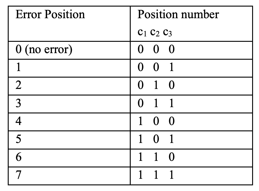
It is evident that if an error occurs in position 1, or 3, or 5, or 7, the least significant digit, i.e., \(c_3\), of the position number must be equal to 1. If the code is constructed so that in every code word the digits in positions 1,3,5, and 7 have even parity, then the occurrence of a single error in any one of these positions will cause an odd parity. In such a case the least significant digit of the position number is recorded as 1. If no error occurs among these digits, the parity check will show an even parity, and the least significant digit of the position number is recorded as 0.
From the above table we observe that an error in position 2, or 3, or 6, or 7 should result in the recording of a 1 in the center of the position number. Hence the code must be designed so that the digits in positions 2,3,6, and 7 have even parity. Again, if the parity check of these digits shows an odd parity, the corresponding position number digit, i.e., \(c_2\), is set to 1; otherwise it is set to 0.
Finally, if an error occurs in position 4, or 5, or 6, or 7, the most significant digit of the position number, i.e., \(c_1\), should be a 1. Therefore, if digits 4,5,6, and 7 are designed to have even parity, an error in any one of these digits will be recorded as a 1 in the most significant digit of the position number.
To summarize:
p1 is selected so as to establish even parity in positions 4,5,6,7.
p2 is selected so as to establish even parity in positions 2,3,6,7.
p3 is selected so as to establish even parity in positions 1,3,5,7.
Steps to construct 7-bit hamming code:
The code can now be constructed by adding the appropriate checking digits to the message digits. Consider, for example, the message 0100 (i.e., decimal 4).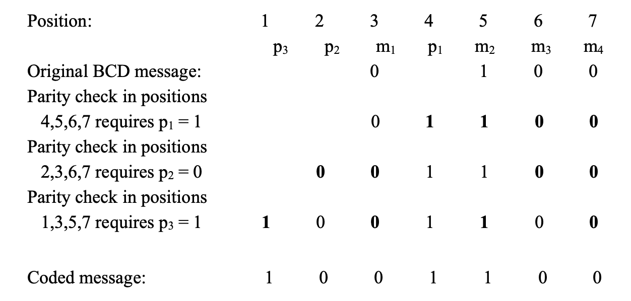
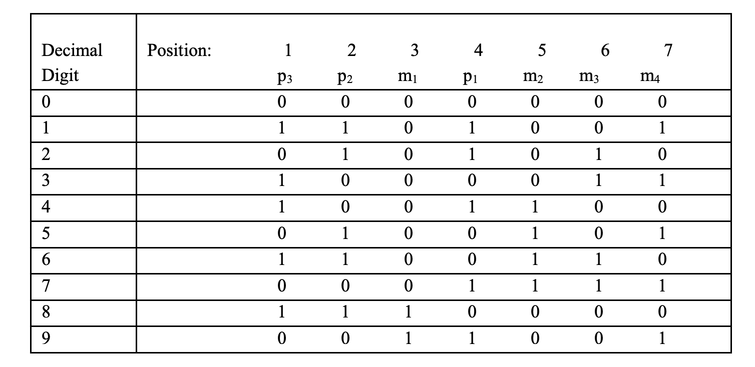
\(p_1\) is set equal to 1 so as to establish even parity in positions 4, 5, 6, and 7. Similarly, it is evident that \(p_2\) must be a 0 and \(p_3\) a 1, so that even parity is established in positions 2,3,6, and 7 and 1, 3, 5, and 7. The Hamming code for the decimal digits coded in BCD is shown in the following table.
Steps to find error location and correction:
The error location and correction is performed in the following manner. Suppose, for example, that the sequence 1101001 is transmitted but, due to an error in the sixth position, the sequence 1101011 is received. The location of the error can be determined by performing three parity checks as follows: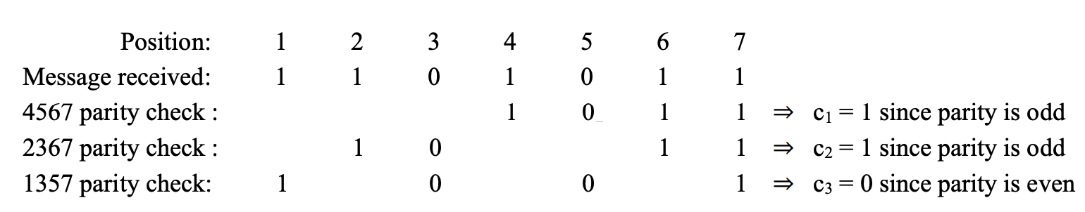
Thus the position number formed of \(c_1 c_2 c_3\) is 110, which means that the location of the error is in position 6. To correct the error, the digit in position 6 is complemented, and the correct message 1101001 is obtained.
Understanding Parity Bit Coverage
Why does \(p_3\) cover positions 1, 3, 5, 7?
| Position | Binary Representation | LSB (Least Significant Bit) |
|---|---|---|
| 1 | 001 | 1 |
| 2 | 010 | 0 |
| 3 | 011 | 1 |
| 4 | 100 | 0 |
| 5 | 101 | 1 |
| 6 | 110 | 0 |
| 7 | 111 | 1 |
Parity bit \(p_3\) (in position 1) is responsible for ensuring even parity for all positions where the Least Significant Bit (LSB) is 1. From the table above, positions 1,3,5,7 have their LSB set to 1, so \(p_3\) covers those positions. If an error occurs in position 1, 3, 5, or 7, the least significant bit of the position number — that is, \(c_3\) — will be 1. If there is no error in any of these positions, the value of \(c_3\) will be 0.
Why does \(p_2\) cover positions 2, 3, 6, 7?
| Position | Binary Representation | Second LSB |
|---|---|---|
| 1 | 001 | 0 |
| 2 | 010 | 1 |
| 3 | 011 | 1 |
| 4 | 100 | 0 |
| 5 | 101 | 0 |
| 6 | 110 | 1 |
| 7 | 111 | 1 |
Parity bit \(p_2\) (in position 2) is responsible for ensuring even parity for all positions where the Second Least Significant Bit (second LSB) is 1. From the table above, positions 2,3,6,7 have their second LSB set to 1, so \(p_3\) covers those positions. If an error occurs in position 2, 3, 6, or 7, the second significant bit of the position number — that is, \(c_2\) — will be 1. If there is no error in any of these positions, the value of \(c_2\) will be 0.
Why does \(p_1\) cover positions 4, 5, 6, 7?
| Position | Binary Representation | MSB(Most Significant Bit) |
|---|---|---|
| 1 | 001 | 0 |
| 2 | 010 | 0 |
| 3 | 011 | 0 |
| 4 | 100 | 1 |
| 5 | 101 | 1 |
| 6 | 110 | 1 |
| 7 | 111 | 1 |
Parity bit \(p_1\) (in position 4) is responsible for ensuring even parity for all positions where the Most Significant Bit (MSB) is 1. From the table above, positions 4,5,6,7 have their third MSB set to 1, so \(p_1\) covers those positions. If an error occurs in position 4, 5, 6, or 7, the most significant bit of the position number — that is, \(c_1\) — will be 1. If there is no error in any of these positions, the value of \(c_1\) will be 0.